NEWS CENTER

Wechat
Communication
Communication
National consultation hotline
0512-66501998
136-5620-9150
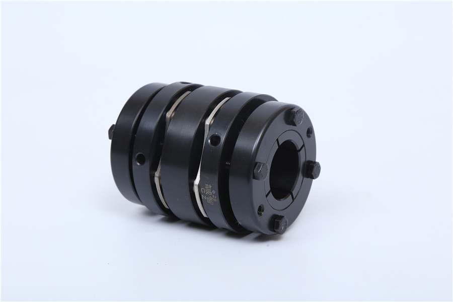
The function of coupling components and the use of quincunx coupling
Date:2021-03-03 Click: 830
The balance level of any coupling component is determined by the square root value of the possible eccentricity of the center of gravity between the inertia axis and the rotation axis of the coupling. The nonuniformity is expressed in microns. The potential unbalance factors of coupling components have been introduced before. The steps to determine the balance level of various types of coupling components and calculate the balance are shown in the calculation example.
(1) The machine manufacturer failed to grade the coupling properly. Shaft offset: when a machine has a long shaft extension or large flexibility, it is sensitive to the unbalanced state of the coupling. The relationship between the bearing load caused by the weight of the coupling and the total load of the bearing: if a machine chooses the light load bearing or the coupling load is basically caused by the cantilever load of the coupling, the machine is more sensitive to the unbalanced state of the coupling. For the machine with cantilever rotor or cantilever load, the unbalanced state of the coupling is usually more sensitive.
(2) The selection of coupling should choose the appropriate balance level, the stiffness of bearing, bearing seat and base: the rotating parts of mechanical transmission system have deformable base or support, which is sensitive to the unbalanced state of coupling.
(3) Whether the measured value of coupling unevenness can meet the needs of any rotating system depends on the performance of each special coupling, which will be determined by the manufacturer of the coupling. While providing equipment, it is suggested that each machinery manufacturer should also draw up appropriate flexible coupling balance, etc;
At present, more and more people begin to use the plum blossom coupling, but in many cases, the details of the installation process are not clear, which leads to the high loss rate of the plum blossom coupling and brings a lot of economic losses. The following is the installation method of quincunx coupling.
(1) Before installation, check whether the two shafts of the original machine and the working machine are concentric, whether the surface of the two shafts is covered and bruised, whether there are sundries in the inner holes of the two half couplings of the quincunx coupling, and whether there are bruises on the edges of the inner holes; if there are bruises, clean the two shafts and the half couplings, and deal with the bruises with a fine file. Then check whether the inner hole diameter and length of the two half couplings are consistent with the original head, body diameter and shaft elongation. In general selection, it is better to make the length of the half coupling at the end of prime mover and working machine less than 10-30mm of its shaft extension.
(2) In order to facilitate the installation, the two half couplings are placed in 120-150 incubator or oil tank for preheating, so as to increase the size of inner hole and facilitate the installation. After installation, ensure that the shaft head will not protrude from the cross section of the half coupling, and it is better to be flush. Measure the half coupling spacing: measure 3-4 points, take the average reading of 3-4 points along the two inner sides of the half coupling, take the sum of the measurement dimensions of the extension section and the two diaphragm groups, and the error between them should be controlled within 0-0.4mm.
(3) Alignment: the dial indicator is used to detect the cross section and outer circle runout of the two half coupling flange discs. When the outer circle of the flange disc is less than 250mm, the runout value shall not be greater than 0.5mm; when the outer circle of the flange disc is greater than 250mm, the runout value shall not be greater than 0.08mm.
(4) Install the bolt: insert the bolt from the outside of the small hole of the flange and from the outside of the large hole of another flange, tighten the sleeve buffer sleeve, elastic washer and nut, and tighten the nut with a wrench. If the installation is not comfortable or the shaft and half coupling are not damaged after disassembly and replacement, it is better to rotate freely without stifling after installation.
In addition, in actual use, check whether the plum blossom nut is loose or falling off before starting the machine. If it is loose or falling off, tighten the nut with a wrench in time.